
This is an important enough point that I felt it deserved its own heading: High speed shooting isn’t just about sports photography; it’s about capturing the perfect moment, regardless of how fast the subject is moving. This is a point I’ve been making since I first tested a prototype of the Casio FH20 a couple of years ago: The difference between the perfect moment of blowing out the birthday candles and one that’s a near miss can be a small fraction of a second. When shooting candids of people chatting and interacting, facial expressions and mouth positions change in literally the blink of an eye. A camera that shoots at 7 frames per second vs. one that only manages 3 frames per second can mean the difference between dozens of "keepers" and just a few.
These ratings on the data tag tell us exactly what minimum ampacity the circuit must be capable of carrying as well as the maximum size the circuit breaker or fuse may be able to protect the circuit against in an overcurrent condition.
The Model 3 is showing 118V @ 12A which is 1.4kW. The same screen shows 1kW/hour being added, but it is rounding down. I need to take a 8 or 10 hour session and total up the numbers.
I would build a custom circuit board, and not use soldermask on the heater side. Instead, I would bond a sheet of pyralux on the face of the heater. Pyralux is Kapton with integrated thermoset acrylic adhesive on one or both sides. 2 mil Kapton has a voltage standoff of 10KV, so electric shock would not be a problem. Bonding can be done in a standard oven using metal plates and clamps (to apply pressure), or with a special heated press.
A vaccum forming table design I looked at used ceramic rods made the same way with reflectors to evenly distribute the heat. I also own an electric kiln designed to heat and temper glass so a page can be taken from that design.
OK … back to the task at hand. Anyone care to comment on how a toaster oven is wired? How about a thermal blanket? None of these use a 12V or 24V switching power supply brick, so how do they do it???
Oh well… That industrial relay has ‘almost’ the same contact ratings of a simple songle srd-05v sl-c relay (specifically the C form/single phase). But I’m sure it won’t last as long as 20y+ in such harsh environment.
Being able to “let go” doesn’t help when your insides are burnt and your heart has ceased meaningful function.
AC may have “won”, but now we need to upgrade to 400 Hz! (smaller transformers, less eddy losses) B^)
The back-EMF voltage generated across the start winding causes a small current to flow in the start winding and potential relay coil, because they are in the same circuit. When the back-EMF has built up to a high enough value (referred to as pick-up voltage), the contacts between terminals 1 and 2 will be picked up (“opened”). This will take the start capacitor out of the circuit.
Older light fixtures won’t necessarily work with energy-efficient CFL and LED bulbs. If you want to stay away from incandescent light bulbs, you might need to replace the whole fixture.
You are correct and if you design this type of solution you already know this. With PCB design, the alternatives are heavier copper, wider traces, plating up copper in the areas that carry heavy current or a combo of any of the three. But you can only go so far with these solutions. Hack apart a known good SSR and I bet they use the exact same solution.
In Japan, People Get Charged Up About Amping Down | Circuit Breaker Parts Related Video:
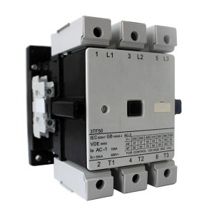
Our aim would be to fulfill our shoppers by offering golden company, very good value and good quality for Ac Contactor Relay , Ac Contactor Relay , Iec Contactor Lc1d115 , We supply skilled service, prompt reply, timely delivery, excellent quality and best price to our customers. Satisfaction and good credit to every customer is our priority. We focus on every detail of order processing for customers till they have received safe and sound items with good logistics service and economical cost. Depending on this, our products and solutions are sold very well in the countries in Africa, the Mid-East and Southeast Asia. Adhering to the business philosophy of ??customer first, forge ahead', we sincerely welcome clients from at home and abroad to cooperate with us.