1.What is the IEC Contactor ?
IEC Contactor is a kind of automatic switching apparatus which uses the electromagnetic iron operation according to the foreign input signal, and frequently connects or disconnects the AC, DC main circuit and large capacity control circuit. Mainly used for controlling motor, welding machine, electric equipment, capacitor group, etc. Its working principle is: when the electromagnetic iron coil to get electricity, electromagnet suction time, driven contactor contact closure, so that the circuit connected.
When the coil loses power, the electromagnet is released under the action of Spring force, the contactor contact is disconnected, and the circuit is cut off.
The contactor not only realizes the long-distance centralized control, but also has high operating frequency, large control capacity, low voltage release protection, reliable work, long service life and small size, and is one of the most important and commonly used components in relay-contactor control system. The basic parameters of contactor include: Rated voltage of main contact, allowable cut-off current of main contact, number of contacts, coil voltage, operation frequency, mechanical life and electric life etc.
Nofuel contactor, the maximum rated current up to 2500A, allow the number of times for 150~1500/h, the total life can reach 15 million ~ 20 million times.
2. HOW TO SELECT AN IEC CONTACTOR
1.Full Load Amperage at Line Voltage
The first item to consider is the load, in amps. This load current is the amount of current required to power the device at line voltage. It is important to know the voltage rating you are going to use, as the current will vary according to the voltage of P = IV (sometimes called P = VA), where P is the work done per unit time, usually expressed in Watts (KW). Ampere (A) is the current in amps and V is the voltage. Since P depends on your device’s power requirements, it will remain the same. If you lower the voltage, you must increase the current to balance the equation and vice versa. In general, you will need to look at the nameplate to confirm the input voltage and full load current (FLA).
2.Contactor Coil Voltage
You should next confirm the control voltage to be used to power the contactor. This can be the same as the line voltage, however often a lower voltage is selected for the contactor for safety purposes. Generally, coil voltages 2
|
AC Control voltage |
36V、110V、127V、220V、380V |
|
DC Contrl Voltage |
24V、48V、110V、220V、440V |
3.IEC Utilization Categories
IEC uses utilization categories, or “codes”, to describe specifically the type of electrical load and duty cycle of the load(s). This is important because these will in part, determine which contactor you use. For example, if you have two applications, both using the exact same motor, but in one case the motor will simply be turned on for long periods of time, while the other will be turned on/off constantly, you will likely use two different IEC contactors for each application. The motor that will be turned on/off constantly will require higher current loads and thus require a larger contactor. Below is a chart of the utilization categories for IEC contactors. Choosing the right utilization code will extend the life of the contactor. An incorrectly specified IEC contactor may work for a period of time, but the lifespan will be severely reduced.
|
AC-1 |
Non- inductive or weak inductive load, resistance furnaces |
|
AC-2 |
Slip-ring motors: starting, disconnecting |
|
AC-3 |
Squirrel-cage motors: starting, disconnecting while running |
|
AC-4 |
Squirrel-cage motors: starting, plug breaking reversing, jogging. |
|
DC-1 |
Non-inductive or weakly inductive load, resistance furnaces |
|
DC-3 |
Shunt motors: starting, plug breaking, reversing, jogging, resistance breaking. |
4.Reversing vs Non-Reversing Contactors
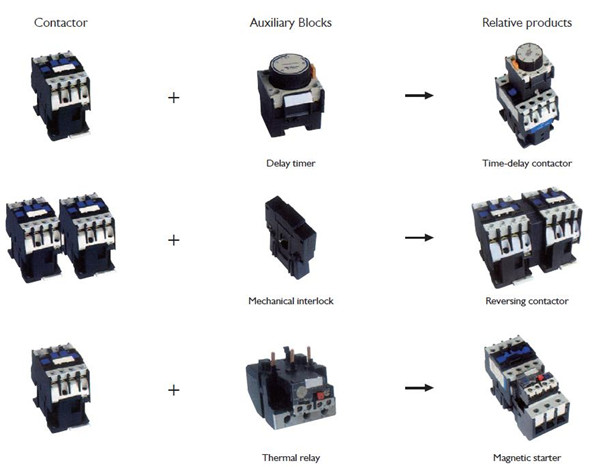
Another consideration is whether the motor operation requires reversing of the direction, in which case a reversing contactor would be required. A reversing contactor is an assembly of two contactors (one for each direction) joined by a mechanical and/or electrical interlock to ensure only one contactor is energized at a time.
5.Auxiliary Contacts
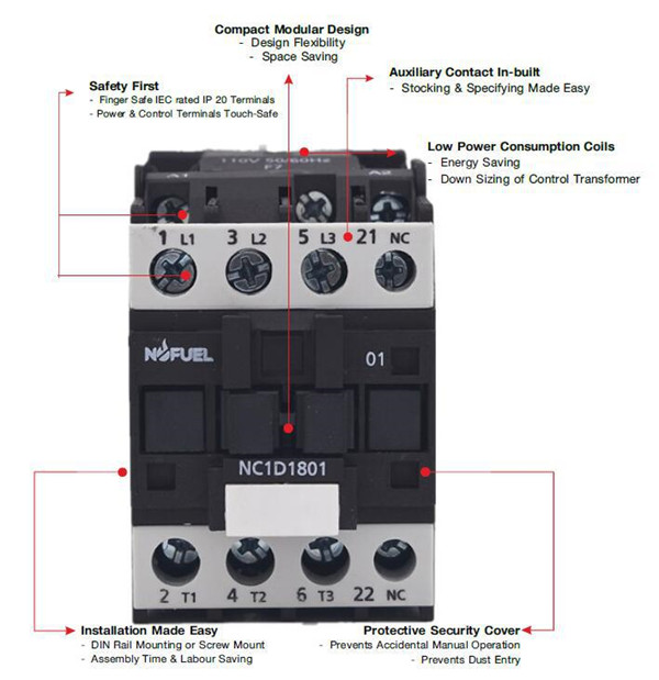
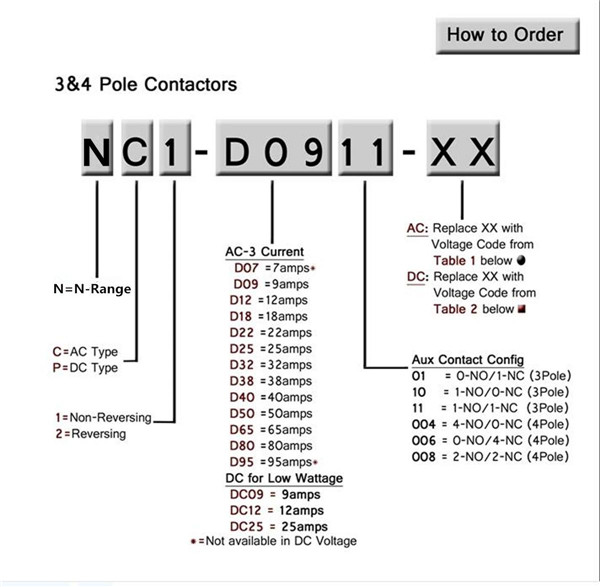
Auxiliary contacts allow additional operations to take place when the contactor is energized. Multiple auxiliary contacts can be added in either normally open (1 NO) or normally closed(1NC) configurations. A good example for using auxiliary contacts would be turning on a pilot light to indicate the motor is running. Adding additional contacts to a contactor is inexpensive and could save you time and money if you take the time to review the operation as a whole. Normally contactor auxiliary contact is : 1NO , 1NC , 2NO ,2NC ,1NO+1NC,2NO+2NC…..
5.IEC Contactor Selection example


Post time: Aug-13-2018
