
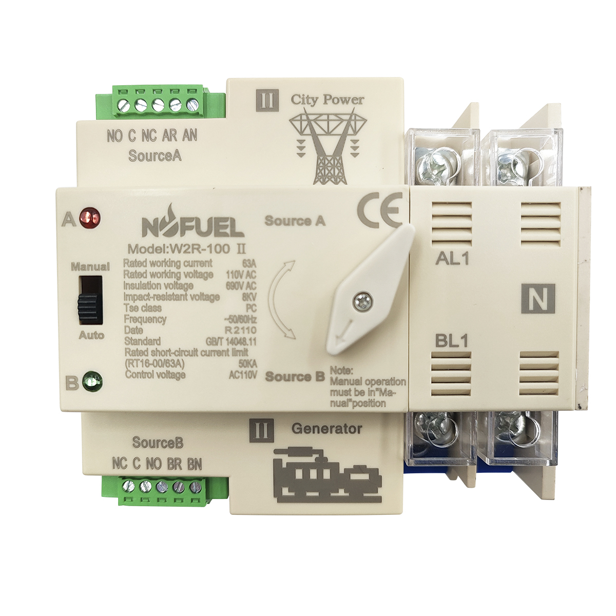
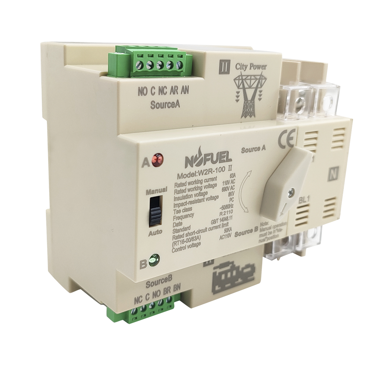
Overview
Series of automatic transfer switches are suitable for emergency power system400v, 60A with AC rated current of 50v or 60HZ, compact structure, reliableconversion, easy installation and maintenance. long life. It is widely used invarious occasions where continuous power failure is not allowed. It can beoperated electrically or manually by ATS, and the controller.
Complies with requirements of Low-voltage Switch Gear and Control Gearspecified by IEC 60947-6-1 and IEC60947-3: functional equipmentandtransfer switch equipment


Wiring mode

Wiring diagram of controller

1. ( Must be connected ) Take zero line and fire
2. ( Must be connected ) Take zero line and fire
3. The power indication signal is passivethe isolation board ( it is recommended tooutput , and the generator signal is takenconnect the load first . then connect the( common ) and ( normally closed )backup power supply )
4. Connect the load end at the lower end ofline from the common control incoming linethe ( standby power supply side ) , Steppedto connect AR ( live wire ) 1 AN ( neutral linewiring
5. There is an isolation board on the loadline from the backup control incoming lineWhen wiring , first remove the isolationto connect BR ( live wire ) / BN ( neutral lineboard . connect the oad and then install
Note : Normal type wiring same as solar type . For solar type , the backup power must beconnected to the city power.
-
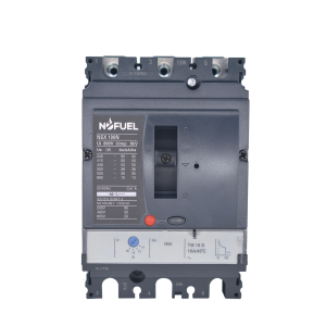
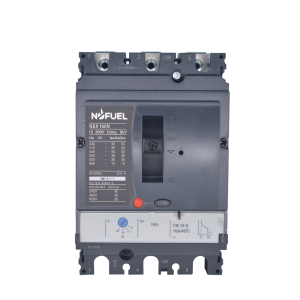
Compact NSX Circuit Breaker NSX100N TM100D LV42...
-
Compact NSX Circuit Breaker NSX100N TM25D LV429...
-
Compact NSX Circuit Breaker NSX100N TM32D LV429...
-
Compact NSX Circuit Breaker NSX100N TM50D LV429...
-
Compact NSX Circuit Breaker NSX100N TM63D LV429...
-
Compact NSX Circuit Breaker NSX100N TM80D LV429...
-
Compact NSX Circuit Breaker NSX160N TM100D LV43...
-

Compact NSX Circuit Breaker NSX250N TM160D LV43...